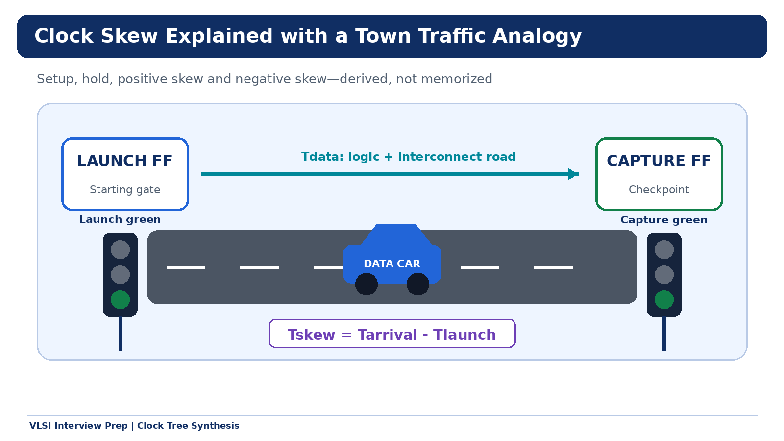
Clock skew is often taught through two statements: positive skew helps setup and hurts hold, and negative skew hurts setup and helps hold. Those statements are useful only after you define the sign of skew and understand the launch/capture timing equations. Otherwise, they become another interview rule that is easy to memorize and equally easy to misuse.
This article develops clock skew from first principles using a town-and-traffic analogy. The analogy makes the intuition memorable, while the equations keep it technically correct. Every calculation uses nominal propagated-clock arrival times — OCV and CPPR are added later in the CTS sequence.
1. The Basic Launch-to-Capture Path
Consider a synchronous path containing two positive-edge-triggered flip-flops:
Launch FF → combinational logic + interconnect → Capture FFThe first flip-flop launches a new data value on the active clock edge. That value propagates through logic and wires before reaching the D pin of the capture flip-flop.
Notation
| Symbol | Meaning |
|---|---|
T(clk) | Clock period |
Tlaunch | Clock arrival time at the launch flip-flop |
Tarrival | Clock arrival time at the capture flip-flop |
Tcq | Launch flip-flop clock-to-Q delay |
Tdata | Combinational logic and interconnect delay |
Tsetup | Setup time of the capture flip-flop |
Thold | Hold time of the capture flip-flop |
Tskew | Capture-clock arrival minus launch-clock arrival |
Clock-Skew Convention
Tskew = Tarrival - Tlaunch- Tskew > 0 — capture clock arrives later (positive skew)
- Tskew < 0 — capture clock arrives earlier (negative skew)
- Tskew = 0 — launch and capture clocks arrive together
Some references define skew as Tlaunch - Tarrival, which reverses the sign names but not the underlying physics. Before saying whether positive or negative skew helps timing, always declare which subtraction you are using.
2. Town Mapping: Clocks Are Green Events, Data Is a Car
Imagine two clock-controlled checkpoints in a town:
| Digital-Timing Element | Town Analogy |
|---|---|
| Launch flip-flop | Starting gate |
| Launch clock edge | Green event at the starting gate |
| Data value | Car carrying a package |
Tcq | Time for car to begin moving after the green |
| Logic + interconnect | Road, junctions and traffic |
| Capture flip-flop | Destination checkpoint |
| Capture clock edge | Green/camera event at the checkpoint |
Tsetup | Preparation time required before the camera event |
Thold | Short exposure time required after the camera event |
The analogy has two timing stories:
- Setup: Can the intended car arrive and settle before the next destination green?
- Hold: After the same destination green, can the checkpoint continue seeing the old car long enough to complete capture?
That distinction — next edge for setup and same edge for hold — is the foundation of synchronous timing analysis.
3. Setup Timing: Arrive Before the Next Green
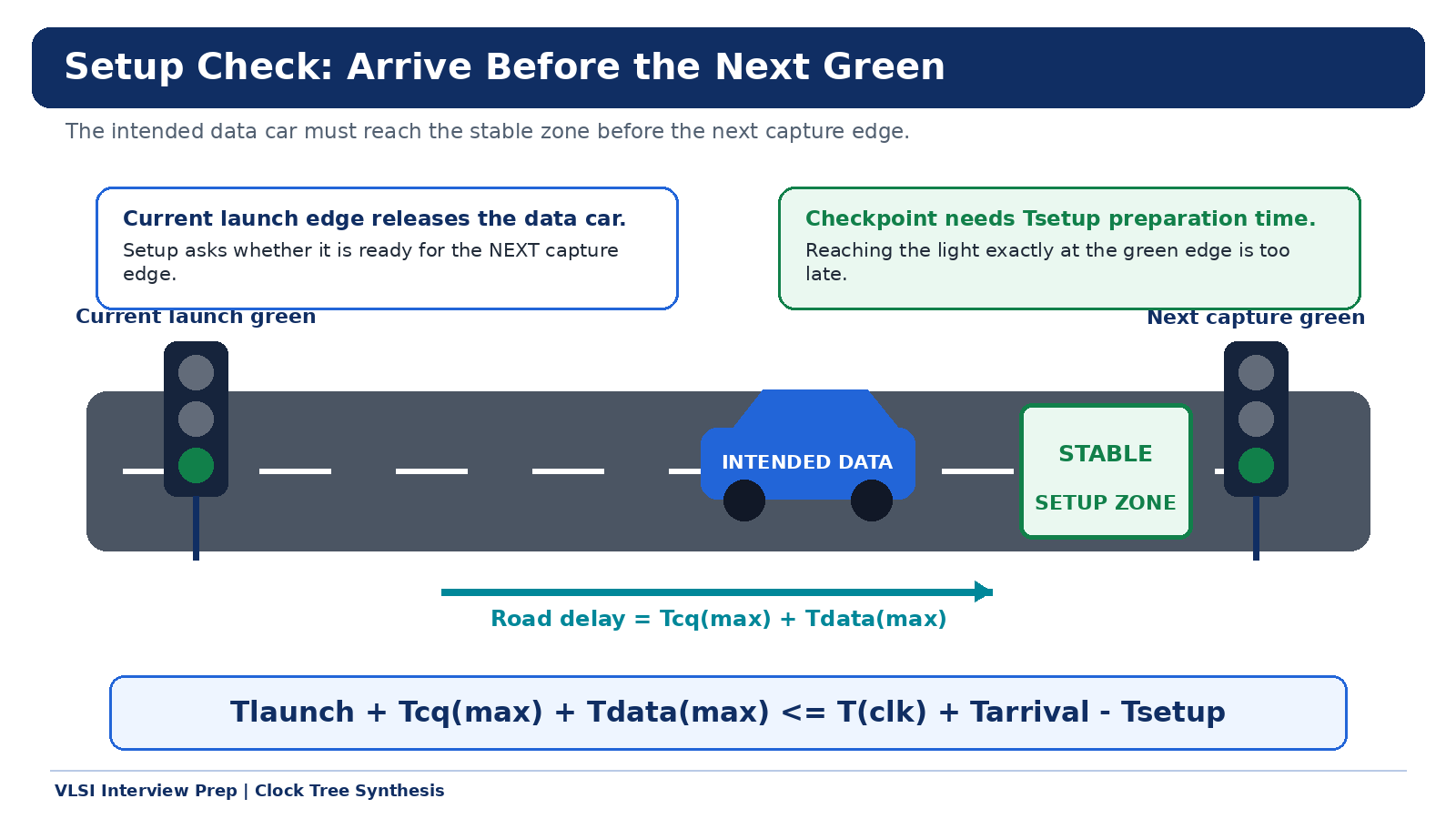
For a normal single-cycle setup check, the current launch edge releases a new data value. That value must reach the capture D pin before the next active capture edge. The car doesn't merely need to reach the checkpoint — it must arrive at least Tsetup before the green because the flip-flop requires input stability before its active clock edge.
Setup asks: is the intended data ready early enough to be captured by the next clock edge?
Setup Equations
For setup we use maximum delays (worst-case late arrival):
Data arrival  = Tlaunch + Tcq(max) + Tdata(max)
Required time = T(clk) + Tarrival - Tsetup

Setup passes when:
  Tlaunch + Tcq(max) + Tdata(max) <= T(clk) + Tarrival - Tsetup
Substituting Tskew = Tarrival - Tlaunch:
Tcq(max) + Tdata(max) + Tsetup <= T(clk) + Tskew

Setup slack = T(clk) - Tcq(max) - Tdata(max) - Tsetup + Tskew
The +Tskew term proves that positive skew improves setup slack.
4. Hold Timing: Protect the Same Green Event
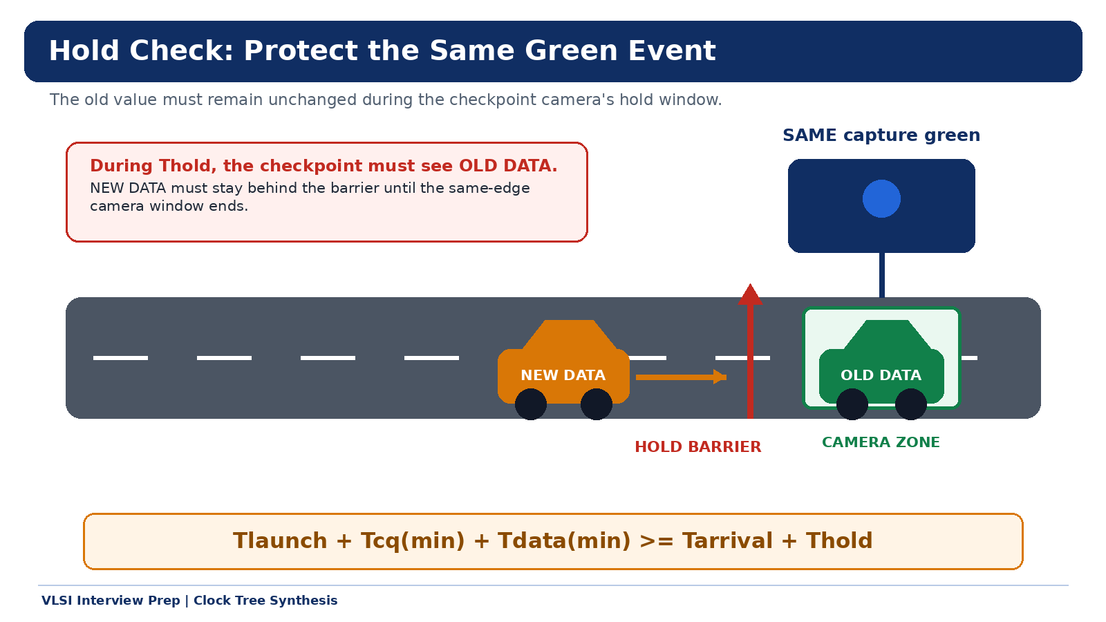
Hold is not a race to the next green. It protects the value being captured by the same capture edge. At the capture edge, the old data is already present at the D pin. The flip-flop needs that input to remain unchanged for Thold after the active edge. Meanwhile, the same launch edge begins releasing new data. If the new value propagates too quickly, it overwrites the old value before the hold window ends.
Hold asks: does the destination continue seeing the old data for Thold after the same capture green?
Hold Equations
For hold we use minimum delays (worst-case early arrival of new data):
Earliest new-data arrival = Tlaunch + Tcq(min) + Tdata(min)
Hold required time         = Tarrival + Thold

Hold passes when:
  Tlaunch + Tcq(min) + Tdata(min) >= Tarrival + Thold
Using Tskew = Tarrival - Tlaunch:
Tcq(min) + Tdata(min) - Thold >= Tskew

Hold slack = Tcq(min) + Tdata(min) - Thold - Tskew
The -Tskew term proves that positive skew reduces hold slack.
Why T(clk) Is Absent from Hold
A normal hold check compares launch and capture events associated with the same clock edge. It does not wait for another cycle, so the clock period does not appear. This leads to an important insight:
Reducing clock frequency can improve setup timing, but it does not normally repair a hold violation.
Hold is fixed by increasing minimum data-path delay, adjusting clock paths, resizing cells, inserting dedicated delay buffers, or changing placement/routing — while rechecking all affected corners and paths.
5. Positive vs Negative Skew
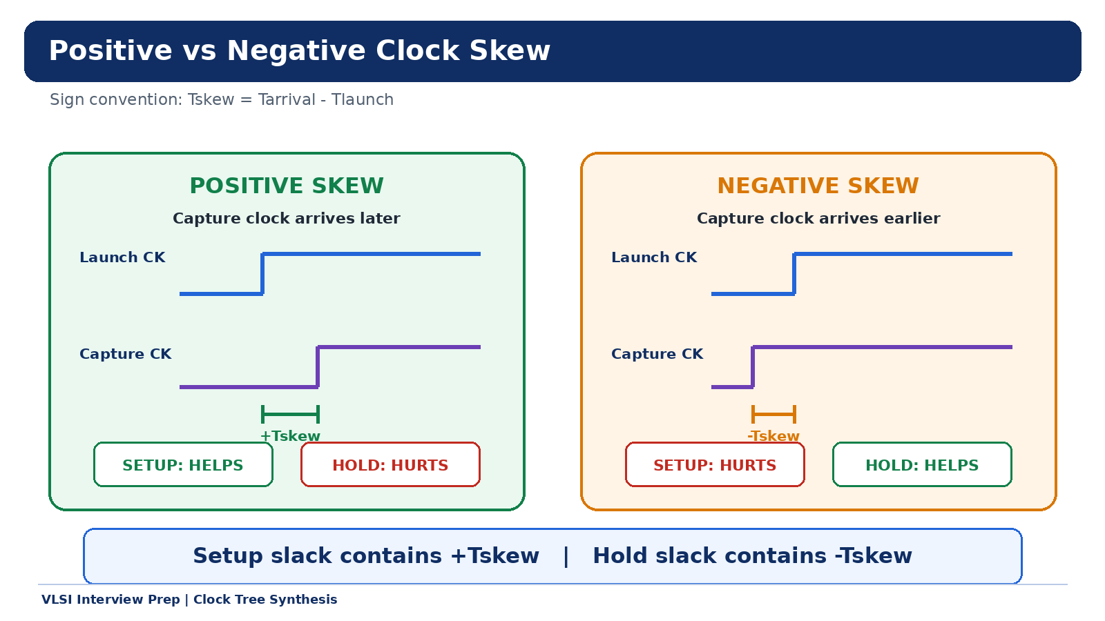
| Condition | Capture Clock | Setup Effect | Hold Effect |
|---|---|---|---|
| Positive skew | Arrives later | Helps (+margin) | Hurts (-margin) |
| Zero skew | Arrives with launch | Baseline | Baseline |
| Negative skew | Arrives earlier | Hurts (-margin) | Helps (+margin) |
Why Positive Skew Helps Setup
If the capture clock arrives later, the data car gets more time to travel from launch to capture. The required time moves later, so setup slack increases.
Why Positive Skew Hurts Hold
The same delayed capture clock also moves the hold window later. The newly launched data must be kept away from the capture D pin for longer. Hold slack decreases.
Why Negative Skew Does the Opposite
An earlier capture edge shortens the time available for setup but causes the same-edge hold window to finish earlier. Setup loses margin while hold gains margin.
6. Manual Numerical Example
Use the following values:
| Parameter | Value | Parameter | Value |
|---|---|---|---|
T(clk) | 1.00 ns | Tlaunch | 0.20 ns |
Tcq(max) | 0.08 ns | Tdata(max) | 0.70 ns |
Tsetup | 0.05 ns | Tcq(min) | 0.04 ns |
Tdata(min) | 0.12 ns | Thold | 0.06 ns |
Max data arrival (setup) = 0.20 + 0.08 + 0.70 = 0.98 ns
Earliest new data (hold) = 0.20 + 0.04 + 0.12 = 0.36 ns
Case A: Zero Skew (Tarrival = 0.20 ns)
Tskew = 0.20 - 0.20 = 0 ps

Setup required = 1.00 + 0.20 - 0.05 = 1.15 ns
Setup slack    = 1.15 - 0.98 = +170 ps

Hold required  = 0.20 + 0.06 = 0.26 ns
Hold slack     = 0.36 - 0.26 = +100 ps
Case B: Positive Skew (Tarrival = 0.30 ns)
Tskew = 0.30 - 0.20 = +100 ps

Setup required = 1.00 + 0.30 - 0.05 = 1.25 ns
Setup slack    = 1.25 - 0.98 = +270 ps  (+100 ps gained)

Hold required  = 0.30 + 0.06 = 0.36 ns
Hold slack     = 0.36 - 0.36 = 0 ps     (-100 ps lost)
Case C: Negative Skew (Tarrival = 0.10 ns)
Tskew = 0.10 - 0.20 = -100 ps

Setup required = 1.00 + 0.10 - 0.05 = 1.05 ns
Setup slack    = 1.05 - 0.98 = +70 ps   (-100 ps lost)

Hold required  = 0.10 + 0.06 = 0.16 ns
Hold slack     = 0.36 - 0.16 = +200 ps  (+100 ps gained)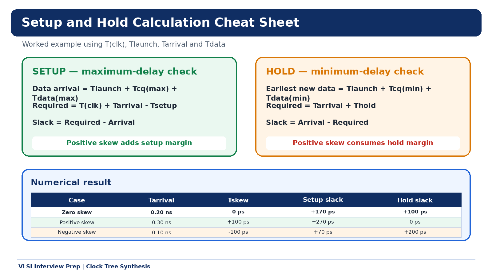
Result Comparison
| Case | Tarrival | Tskew | Setup Slack | Hold Slack |
|---|---|---|---|---|
| Zero skew | 0.20 ns | 0 ps | +170 ps | +100 ps |
| Positive skew | 0.30 ns | +100 ps | +270 ps | 0 ps |
| Negative skew | 0.10 ns | -100 ps | +70 ps | +200 ps |
Each 100 ps of skew transfers exactly 100 ps between setup and hold budgets. This is the skew trade-off in its purest form.
7. Useful Skew: Intentional Budget Transfer
CTS is not always trying to force every sink to have identical arrival time. A controlled clock-arrival difference — useful skew — can deliberately redistribute timing margin between paths.
For example, delaying the capture clock of an endpoint may help a critical incoming setup path. However, the same change can:
- Reduce hold margin on that incoming path
- Change the setup budget of paths launched by that endpoint
- Affect upstream clock load and neighboring skew
- Behave differently across voltage, process and RC corners
Useful skew is therefore not free timing. It is a deliberate budget transfer that must be validated for setup, hold, slew, capacitance, clock power and all MMMC scenarios.
# ICC2: Enable useful skew / CCD
set_app_options -name clock_opt.flow.enable_ccd -value true
set_app_options -name cts.compile.enable_local_skew -value true

# Constrain maximum allowable useful skew
set_app_options -name ccd.max_skew -value 0.100
8. Common Interview Mistakes
Mistake 1: Stating the skew rule without defining its sign
Always begin with Tskew = Tarrival - Tlaunch, then explain whether the capture clock is later or earlier.
Mistake 2: Treating hold as a next-cycle check
The basic hold check protects data captured by the same edge. This is why T(clk) is absent from the basic hold equation.
Mistake 3: Using maximum delay for hold
Setup checks latest data arrival → maximum delays. Hold checks earliest new-data arrival → minimum delays.
Mistake 4: Assuming clock-buffer upsizing only changes slew
Changing CKBUF4 to CKBUF8 may improve transition, but it also changes cell delay, upstream capacitance, branch latency and skew. Every clock ECO must be followed by setup and hold analysis across all relevant corners.
Mistake 5: Assuming all endpoint skew is equally important
Timing is affected by the launch/capture skew of actual communicating register pairs. A single global maximum-skew number does not describe every path's timing risk.
9. Interview-Ready Answer
I define clock skew as
Tarrival - Tlaunch, where Tarrival is the capture-clock arrival time. Positive skew means the capture clock arrives later. It increases the setup budget because the launched data receives more time to reach the capture flop, but it reduces hold margin because the same-edge hold window also moves later. Negative skew does the opposite. Setup is a maximum-delay, next-edge check; hold is a minimum-delay, same-edge check.
10. Final Takeaway
The town analogy reduces the topic to two questions:
- Setup: Is the intended car inside the stable zone before the next checkpoint green?
- Hold: After the same checkpoint green, does the camera continue seeing the old car until its short exposure window has finished?
Once those two scenes are clear, the equations explain the skew trade-off naturally:
Setup slack contains +Tskew
Hold  slack contains -Tskew
That is why positive skew helps setup and hurts hold under the stated convention — and why useful skew must always be applied with full setup/hold awareness across all corners.
The equations above describe the common same-frequency, same-active-edge, single-cycle register-to-register case. Multicycle paths, opposite-edge paths, generated clocks, clock-domain crossings and advanced variation analysis (OCV, CPPR) require their own edge relationships and constraints.
Get the complete CTS Positive & Negative Skew manual calculation guide as a printable PDF (7 pages) — perfect for interview prep and quick reference.